Solar Thermal
Current Solar Heating Syatems:
Heating Systems: 200sqft active solar hot air collector, 70sqft. evacuated tube tracking liquid collector, all integrated with a 3000 lbs water storage tank. Backup
DHW heat is a 40 gallon electric water heater. The two 4500W elements have been re-wired in series to drop down the total load for BOTH of them to 2250W. This is part of the load "flattening" I have
done to accomidate the off grid capabilities when on inverter backup power. Reducing peak loads is an important part of energy efficiency and management. At this time, none of the evacuated tube or
hot air collector heat is used in direct connection for the SAHP geo assist. I have one more evacuated 60 tube ground array to bring on-line before I directly heat the EW for the geo heat pumps.
PLEASE keep in mind that allot of the photos below show the history and evolution of the solar systems through time.
200 Sqft Hot Air Collector after initial completion back in December '94.
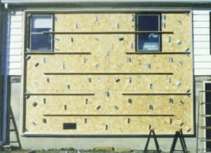
Photo shows air flow channels and baffling to cause turbulence in the air flow to improve heat transfer from aluminum collector plate to air flow.
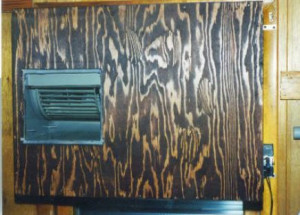
Blower and its box where hot air is pulled from collector. Blower puts out 600-800 CFM. Maximum air temp is around 140 DegF. Blower box is mounted in old window hole enclosed behind collector.
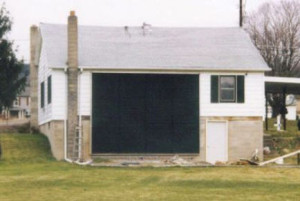
The hot air collector pictured, was the first project chosen for the homes energy makeover. I chose this as the first, because the impact to the other areas of the
house were minimal, yet the effect on oil usage would be large. I decided not to use glass as the glazing for several reasons. Weight and danger from breakage due to the size of the collector and its
location, were two main factors. Another was that I wanted something more transmittive than glass. Ultimately I chose Teflon. Its durability under sunlight, "zero weight", extreme clarity to the suns
energy (96%+), were the major benefits. By using a film type glazing, the support structure for the glazing mounting would virtually disappear. The aluminum collector itself is comprised of three
sheets of corrugated Aluminum 16’ x 4’ running horizontal. When the collector is finally complete, it will have three layers of Teflon, with three separate air spaces. At present it has only one.
Even with three layers, 85% solar transmission will be maintained. Currently the output air maximum is around 140 deg’s F at a flow rate of about 600 to 800 CFM.
The size of the hot air collector was determined by the general rule of thumb of 1 sqft of collector for each 10 sqft of heated floor space. Approximately 2000 sqft to
heat, therefore 200 sqft of collector. Since the photo above, a concrete patio has been added. During the heating season, which is when the hot air collector is active, I put aluminum reflectors on
the patio which bounce extra solar radiation onto the collector. The gains are about 10 to 15 degrees in output air temp. The collector did not have any storage initially tied to it. This was to come
with the introduction of a year round liquid collector. The goal was always to put a 3.5 meter parabolic tracking collector for the liquid part, coupled with the appropriate size water storage. But
the parabola project was not going to be complete, perhaps for a long time, so I opted for a simple 4’ x 8’ copper flat plate collector. This would allow the whole system to be completed.
Operationally, all testing could be completed and all "bugs" could be eliminated. The benefits of storage could start to be realized, although the heat values into storage would of course be much
less than with the dish unit.
The hot air collector worked so well, even with its single layer of Teflon, that it was necessary to extract some excess heat from it once the liquid storage and
liquid system came on line. This was done with the addition of a heat exchanger between the air collector and the blower. In the long run, the extraction of "extra" energy from the hot air collector
would not be necessary. When the basement level was complete from an insulation and drywall perspective, about 50% to 75% of the hot air from the collector would be shot down there directly
eliminating upstairs overheating. Secondly, the box temperatures are expected to average in the 100+ range most of the time when the dish comes on line, that only a minimal amount of heat be gained,
not enough to justify the pump energy used for the extra circulation.
The tracking evacuated tube collector which has been on line since 9/21/2004, can be viewed as an intermediate project, replacing the 4'x8' flat plate collector. Box
tempatures are already substantially higher. This year, Winter 2004-2005 I am not using reflectors and I am trying to get the extra Teflon glazings in place, finishing the original design
concept.

First liquid collector went operational back in June '99. Collector was recently replaced by collector pictured below.
High efficiency evacuated tube collectors went on line 9/21/2004. There are two units mounted on the East-West tracking array. Initial data looks very impressive. The total weight of the array is about 550 pounds and measures about 7'x12.5'.
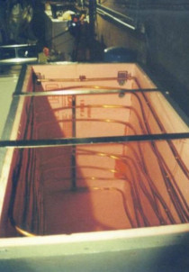
The water storage box pictured, is made of 1-1/2" plywood (2 - 3/4" material laminated together) coated inside with epoxy paint and fiberglass on all seams. It stands 4’ tall, about 5’ deep and 30" wide. The exact inside volume is 46.32 cubic feet @62 pounds per cubic foot is 2871 lbs. With some copper, bricks and steel inside I round it off to 3000 lbs. of water or 3000 BTU’s per deg. F. change. The box has 120 feet of ½" copper tubing which serve as a heat exchanger to put heat into the box as well as take it out. When the exchanger fluid is in heat delivery mode, it flows from the top down. When in extraction mode, it flows from the bottom up. This gives the exchanger a degree of counter flow functionality, since the box is always warmer at the top than at the bottom.
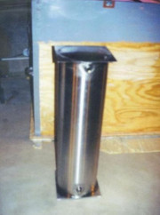
The 20 gallon stainless steel tank in the second photo sits in the center of the box in an upright position. Well water on the way to the oil fired water heater, flows into the bottom fitting of the stainless tank and exits the top. Having a "cold" source in the center of the box, and the hot coils on the sides of the box, serves to set up a convection loop which further increases heat transfer efficiency.

The third photo shows the completed box. With the 1" extruded polystyrene insulation (R5) inside and the 1" fiberglass insulation (R4) on the outside, plus a little R value from the wood itself, the bottom and sides are rated at R10 total. The top is 3" of foil faced polyurethane (R22). Approximately 15 gallons of ethylene glycol (regular car antifreeze) was added to the water in the box for bacteria control. This also doesn’t hurt when it comes to corrosion resistance. The Brock oil fired water heater sits to the right of the box, the Rheem air handler over the top, and the 275 gallon oil tank to the left. The box was designed to fit right in the space created by those three system pieces. The air expansion tank, pressure gauge, fill ports (in and out), and some of the plumbing are located on the front end of the box. The Rheem air handler above, was fitted on the front with a Snowmax heat exchanger, which is how the heat from the box is transferred to the air on its way to the main heating coils for the homes space heating. The warmer the air before it hits the main coils, the less the oil burner runs. This setup reflects the systems before the geo was in place. Currently, the solar box heat preheats DHW only.
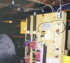
The fourth photo shows the pumps and control relays for all the solar collectors.

Bock Oil fired water heater installed in December of '95. As mentioned above, the solar water storage and liquid collector didn't go on-line till June of '99. The little clock seen on the top of the water heater, only runs when the oil burner itself runs.
The oil fired water heater shown above, is a Bock 32 gallon, with a .75 GPH nozzle installed in the burner. The heater is tied to a Rheem air handler which provides the space heating for the home. A Snowmax heat exchanger was placed on the front of the air handler to preheat the air on its way to the main heat exchanger. The fluid running through the Snowmax is solar heated from the box water storage. A 20 gallon stainless steel tank within the box (see storage picture) preheats the well water before it goes to the O.F.H.(oil fired heater). The clock shown in the photo sitting on top of the heater, only runs when the oil burner is running. It is reset everyday, so the total oil burner runtime can be recorded each day. This piece of data coupled with storage temps., provides much of the information for the solar systems effectiveness (see detailed graphs) in reducing oil and electric usage. The O.F.H. ‘s plumbing is such that it can be isolated for cleaning or failure with the twist of two stainless steel ball valves. The box water storage also has the same capability. The entire system is designed in such a way that the failure or maintenance of one major part does not effect another, so you always have a source of heat. The vent pipe for the O.F.H. has a Magic Heat heat exchanger in the stack pipe which extracts heat from the waste gases. The chimney temp usually is between 150 and 300 degs. F., which is "cool" for an oil burner.
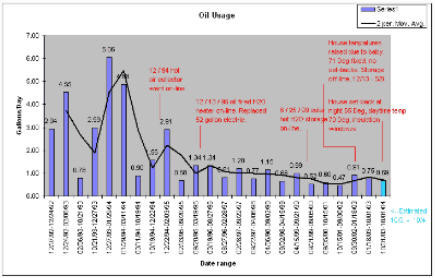
This graph shows oil purchase dates and amounts. The number at the top of each bar is the gallons per day used for that period of time.
The solid line is a moving average trend line. Key system changes are noted above relevant time period.
Last Updated 6/27/2026
2024 is another PV Record Buster !!
Its official! 2024 is also a PV production record buster. The main tracking array produced 18.503 MWH's. However, the gorund test array added another 4517 KWH's to that, totaling 22.847MWH's, an increase over last year of .173 MWH's total.
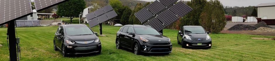
UPDATE 6/23: Kia Nero traded in for Kia EV6.
UPDATE 9/22: New 40+ KWH battery backup installed with coming 4.6KW direct feed array. See details under 'My Solar Home', Solar PV.
********************************************
BLOG site for "open" topic writings, by myself!
https://nosidestaken.blogspot.com/2025/01/a-republic-if-you-can-keep-it.html
https://nosidestaken.blogspot.com
********************************************
Where to Find Us:
www.WeAreSolar.com (Fitch Consulting)
1072 Fowlersville Rd
Berwick, PA 18603
Phone: 570-752-4827
Update 6/2026: Peak solar production for my house in one day is about 142.7KWH.
What's New
01/12/2021 My new GEO heat pump is finally installed. I have been "tweeking" it until today, 01/16/2021. It works GREAT!! Unlike it predecessor's, it actually performs up to its submittal sheet. LOVE IT!!

I finally finished my electric overhead to underground conversion along with the transformer upgrade (15KW to 50KW).
May Monthly Production Record Gets blown away in June at 2517KWH !!
Made changes to my PV tracking system. The main PV inverter was upgraded from an SMA SB-US-8000 to a Fronius Primo 11.4 (11,400 watts). Additionally, the PV arrays were upgraded with 20 SunPower 327 watt modules leaving 16 of the original Canadian Solar 255 watt modules, bringing the total output of the array from 9.18KW to 10.620KW. The combination of the inverter upgrade coupled with the array KW upgrade, should generate an additional 2 to 3 MWH a year. I hope this will compensate for the increased cloudiness being produced by Green House Gas Heating Climate change. It took a fair amount of work to do all this....
UPDATE: All 36 modules are being changed out which will result in an array output of 11,772 KW. On a very sunny year, 20 MWH should be within reach.
PV Yearly Production Numbers
2022-2024. Yearly numbers are running around 22 to 23MWH's a year with ground test array added.
2021 PV Production is 19.325 MWH which just misses the record breaker last year. Across the year, 2021 was much cloudier but crazy super sunny March made it almost even. Since the system has been running, we have produced over 129 MWH's total.
2020 PV Production is 19.375 MWH which is a new record buster.!! The only month that did not gen more than last year was October. Our usage was up due to more driving and general increases, which the increase in production was able to satisfy. That production defers about $2000.00 worth of power from the grid.
2019 PV Production is 16.787 MWH.
2018 PV Production is 12.463 MWH.
2017 PV production is 14.293 MWH.
2016 PV production is 15.629 MWH.
2015 PV production is 14.543 MWH.
2014 PV production is 7.711 MWH, first year partial production. 9.374 MWH were produced through the entire startup test phase of the system before certification.
2019 production was a record breaker, do to the upgrade being active for 1/2 the year along with being decently sunny. Most likely, if the array upgrade had been active for the whole year, 17 or 18 MWH's would have easily been had.
2018 production was the worst production ever, not only for PV but for all solar. The rain and cloud cover was unpresidented! WE blew right through the 13 Megawatt range and landed in the low 12's. An increase in array capacity might be necessary to adapt to the GH GH'ing realities causing climate change, to resore a slight electrical surplus.
2017 production down 1.34 MWH from last year. All months produced less except for December which is the cloudiest month of the year.... Ironic...
Electric car miles for the fifth year are 15863 saving 690 gallons of gas at an avoided cost of $1932, bringing the five year total to $9172.00. Covid-19 reduced mileage, but a third car (Bolt) and a third driver beginning in August, over turned the shortfall.
Electric car miles for the forth year are 14037 saving 610 gallons of gas at an avoided cost of $2014.00 bringing the four year total to $7239.00. Gas went up and down over the period.
Electric car miles for the third year are 13,220 saving 575 gallons of gas at an avoided cost of $1955.00 bringing the three year total to $5225.00. Gas prices steadily climbed throughout the year. Total number of gallons not used stands at 1790.
Electric car miles for the second year are 14,830 saving 645 gallons of gas at an avoided cost of $1870.00 bringing the two year total to $3270.00. Not bad for only 2 years at fairly low gas prices...
Electric car miles for the first year ran about 13,000 miles of energy free driving. The gas saved which would have been burned by the car that the Leaf replaced equals about 570 gallons at an avoided gas cost of $1400.00.
Total mileage across the three years equals 41,050 miles. At a gross electric usage of 3 miles per KWH year round, this translates to 13.68 Megawatt hours of electricity, or 4.56 Megawatt hours per year. With the addition of the Ford C-Max plug-in Hybrid over the last year, the total transportation electric load is increased by about 2 megawatt hours more, bringing the household trans electric yearly load to about 6.6 megawatt hours.